Sunday 6 July 2014

The Results... Sunday, 29 June

Things didn't go our way on Sunday. From the beginning we were using motors that are a few years old. They seemed to be running ok in the lab but one of them was showing symptoms of a bad bearing. We thought it fixed itself and remained optimistic. On the last day of the competition as we were approaching the regenerative braking challenge, we decided to see how applying reverse current would change our regeneration. Instead of amplifying the recharge, it caused that bad bearing to cease up. This caused a catastrophic motor failure on that bad motor I was talking about. Now, one motor was acting like a break. I heard what sounded like wires arching and confirmed later that there were sparks coming from the bottom of our locomotive. We quickly realized we couldn't complete the regenerative braking challenge. We decided to skip the regen and continue to the traction and sound challenge. With our bad motor acting like a brake and making a tremendous amount of noise, we made it up the hill reaching a max speed of ten kilometers per hour. Speeds reached on Saturday hit the 15 kph mark with room to go but 10 kph on the traction challenge wasn't going to cut it. We knew we had lost the entire competition and waited for the results to come in. 

We ended up coming in 3rd out of four teams. We had a lot of issues surface the last week of building and then a motor failure the last day of competition. I believe that if we had our motor in working order we could have won the regenerative braking challenge and possible the traction challenge. But, we'll never know, until next year. 

I want to say thank you to all who have supported me in this trip and I am happy to say that I have been asked to return next year and help build the next locomotive. I plan on coming back. Cheers Mates!

June 28 and 29 - The Competition - Just Pictures (not mobile friendly)

The pictures below were taken from my phone. 
Here is a dropbox link to more pictures taken by two others. 


Friday the 27th

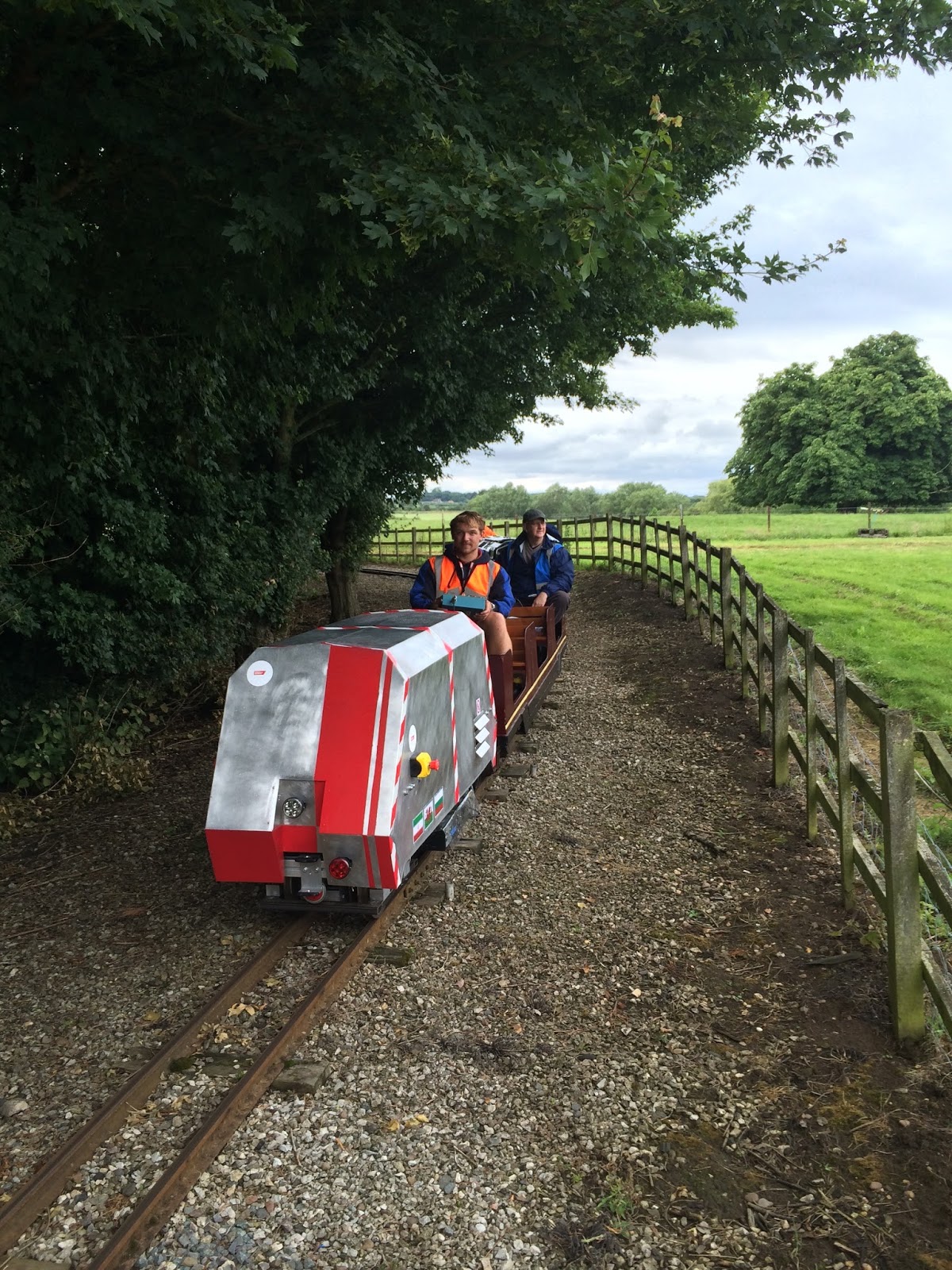
We were supposed to be leaving the school at 18:00 hours on Friday the 27th. The locomotive still wasn't tested. From last post, most of the components were installed but nothing was turned on and no power was sent to the wheels. We stayed in the lab till 03:00 Friday morning but couldn't not get the components ready to run. We cam in at 08:00 hours that morning to run more tests and to get help with the circuit components. While Ivan and Hammed completed the circuits, everyone else was putting the last touches on the locomotive. One task in particular was the pressure regulator for the air compressor. The only way for it to be accessible was to install in on the bottom of the chassis. The compressor wasn't meant to be disassembled so the regulator wasn't mount friendly. So I found a piece of wood, bored out two holes to attached some T-nuts to it so it could be attached to the extruded aluminum chassis. Then, I used some wood screws to screw it into the wood. Worked perfectly. Anyone can complete a task with the right tools, instructions, and components. It takes an engineer to complete a task WITHOUT the right tools, instructions, and components.


I wasn't the only one doing work. Thursday, the aluminum body was made and painted. Friday, we spent time doing the final fittings, drilling hols for the bolts that were outside the designed area, and bolting in the mounting brackets used to connect it to the chassis.


Next, we realized that we didn't have enough time to finish the testing in the lab and we needed to get to the track. So we decided to pack up and head to Stapleford Miniature Railway.

June 23 through 26

The suspension pieces were complete. A chevron suspension was designed to dampen the vibrations from the track.  These pieces were milled and tapped for screws individually. This was an all day event, tapping the holes drilled into each piece. 


June 16 through 20

This week was quite busy with a lot of little projects going on all at once. For our regenerative braking, we used super capacitors. At 2.4 volts, we used 20 of them to reach 48 volts. These needed to be soldered together in series in a configuration that would fit in the 'wind tunnel' we built to keep a few components cool during operation. We also have to make a lot of our cables by hand. You can see the 15 terminal plug that I wired. One of the most difficult soldering jobs I've ever done. Which doesn't compare to what Ivan does. The multiple circuits you see are logic boards that convert voltages and filter currents coming from our sensors and is a bridge between the remote and the motor controller. Constantly we're having to drill holes in the chassis to insure stability in the attached pieces. The corner brackets you see are not very reliable since they only restrict movement in two of three axis. So, if not anchored to the chassis with a semi-through hole it will continue to slide under high stress.


And here we have the remote control box. We looked through multiple storage bins to find the perfect box to house our components. It has 6 colored LEDs, a three point keyed switch to indicate directions forward and backwards and an off position to apply the air brakes, a two way switch which would turn speed mode on and off, a push button for the horn, a flip switch to change power sources from the capacitors and batteries, and the throttle joystick. The three LCD displays are used for speed, supercap voltage, and an auxiliary display.  


Below is one of the air brakes and the axle without the wheels. On the left side of the axle is the brake rotor. The air brake attaches with a mount on the steel plate. 


June 9 through 13


Pieces are starting to come together. The locomotive is starting to take shape. The next piece to fit to the chassis mount for the batteries. The trick here is we had four twelve volt, 90 amp hour batteries. We had some spare steel so we decided to make a platform to attach to the chassis. This worked perfectly.

As we were assembling other pieces, more fabricated bits were coming in from the workshop. Among those bits were the steel plates for motor mount/axle mounts. Here, the motor connects to a gear which is attached to the axle that runs through the plates which is attached with bearings. Also you see the hollow steel frame where the suspension will connect it to the chassis. 


Saturday 21 June 2014

June 2 through 6


This is new suspension for the locomotive. It can support over 400 kg. I weigh 105 kg. In last years competition, the team suffered point deductions due to the lack of dampening in their frame. This year they went with solid rubber spacers to act as a suspension. It seems to work great! 


This week I also spent time on the controller, learning more about microbasic. It's a steep learning curve and since no one here knows how to program in this language, it's all up to me to learn it. I was able to make the motor run with the script using a throttle plugged into the controller. The next step in programming the controller was to write a script for regenerative braking. This is when the locomotive is going downhill or braking. In order to collect the most energy, the motors need to be supplied with enough power to eliminate the torque restraint. To help with this task I used an online example provided by RoboteQ where they had regenerative braking on an electric scooter. To test the code, we needed to build a rig to house the motors and connect a chain to both motors. One will act as the driving motor and the other will be used to provide resistance or make it speed up as if it were going downhill. In order for the code to work, the tachometer needed to be attached to the motor. So, as simple as it sounds, we placed the tachometer in it's brace on some pieced of wood and attached a plastic piece to the motor axle with some tape. It was just fine for low speed testing.